From "Dynamic" to "Stable": OpenArm Open-Source Robotic Arm CAN Communication Link Optimization Guide
Copyright Notice: You may reproduce or quote this article with attribution to Chengdu Kunhong Electronic Documentation Center and with a preserved original link. Original link: https://docs.kunhong-elec.com/zh/applications/robotics/openarm-link-optimization.html
In the open-source robotics field, OpenArm is a very successful project. From teaching and research to personal development, it provides great reference value.
From an engineering product perspective, however, a system usually still needs careful engineering refinement to evolve from "Works" to "Reliable".
During our testing and debugging of OpenArm, we found several obvious issues in its CAN bus physical layer. These problems may not be obvious in everyday scenarios, but they can introduce potential risks in more demanding communication environments.
Summary
At first glance, the complete machine performance looks fine. Yet users often report various issues while debugging.
After further inspection of the CAN bus, we identified several typical (but easy-to-overlook) problems: 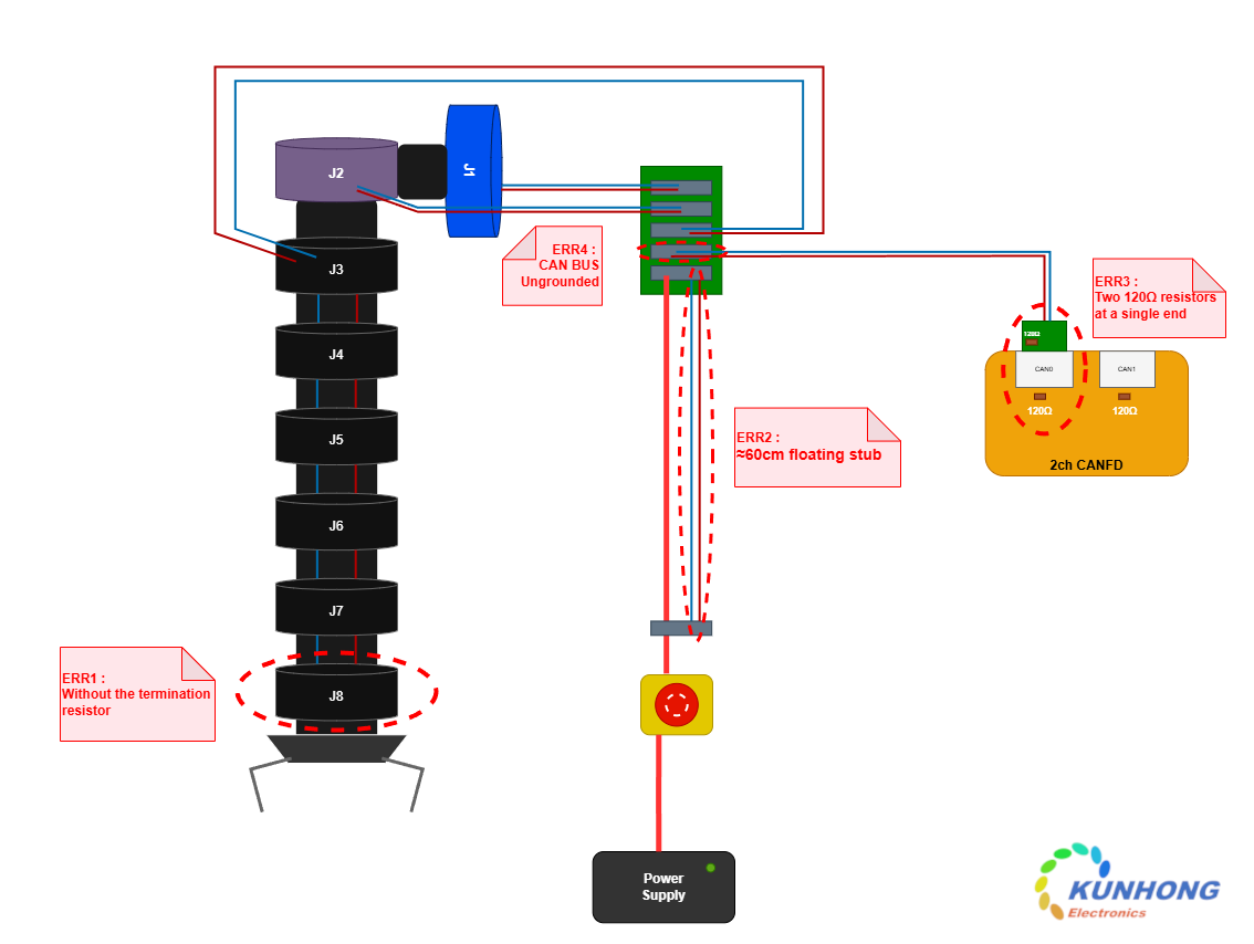
- Incorrect CAN termination resistor placement (the open-source documentation provides no guidance on termination resistor configuration)
- An extra redundant CAN line in the power cable creates a 60 cm dangling CAN stub
- The motor's CAN_GND is not directly connected to the CAN adapter
Waveforms Tested Under the Original Open-Source Design
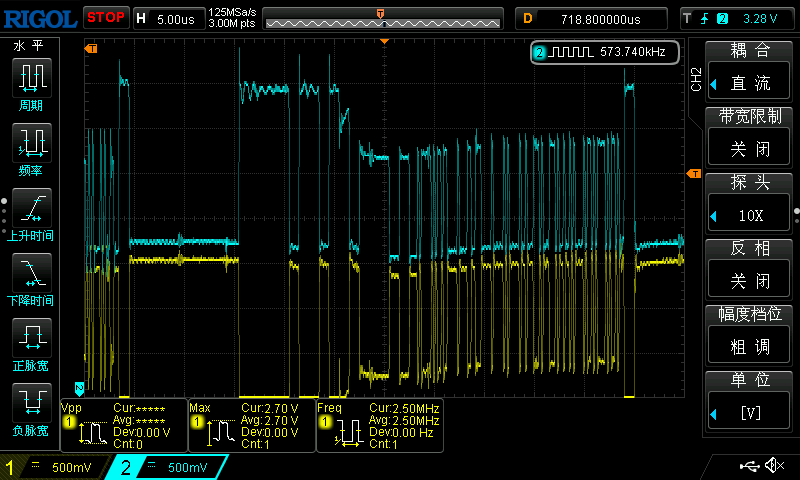
From oscilloscope measurements (with the German PEAK PCAN-USB FD PRO), you can see:
- The waveform has severe signal distortion
- Reflections and ringing are severe
- There are many error frames (leading to BUS OFF disconnection errors)
This article analyzes the issues above and provides recommendations for improvement. We also review the current communication status of the full machine.
1. CAN Bus Topology Analysis
1. Main trunk structure is basically reasonable
First, it is worth affirming that the CAN connection method for the main arm portion is generally reasonable.
Its structure largely follows the recommended CAN bus Daisy Chain topology: 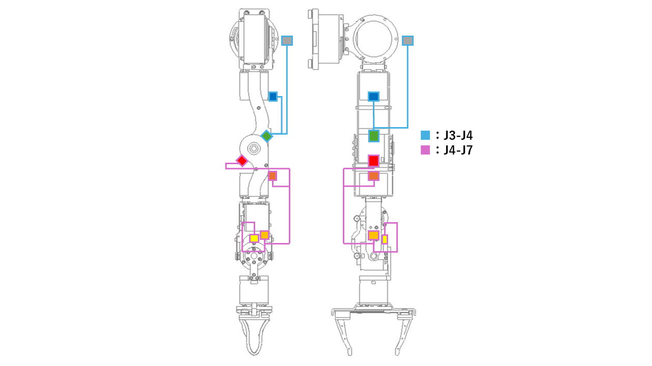
Although J1 and J2 motors belong to a branched structure, the branches are short (less than 30 cm), which aligns with recommended CAN bus practice.
2. Overly long dangling stub
There is a typical wiring issue in the overall system: a 60 cm dangling CAN stub created by a redundant CAN line in the power cable. 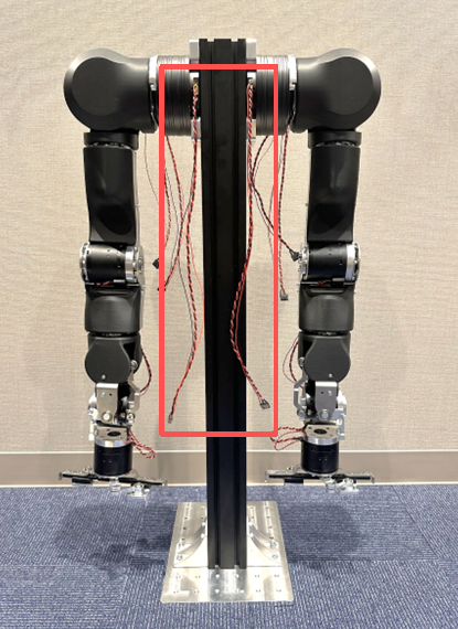
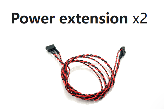
- The power cable includes the CAN signal lines, but no CAN node is connected on the power adapter side
- This creates a 60 cm long dangling CAN stub from the HUB wiring board to the power connector
- The stub runs in parallel with the power line
In a CAN network, a long stub is one of the most common stability killers. It can cause:
- Impedance discontinuity: reflections occur when signals meet impedance changes; the longer the stub, the more obvious it is
- Signal ringing: reflected signals add together and cause ringing
Therefore, this 60 cm dangling stub clearly does not meet engineering requirements.
2. Termination Resistor: the Hidden "60 ohm Trap"
Another easy-to-overlook issue is termination resistor configuration.
When debugging a CAN network, many people measure the resistance between CANH and CANL using a multimeter.
In theory:
- Each end has a 120 ohm termination resistor
- So the measured result should typically be 60 ohm and considered "normal"
However, for OpenArm, the measurement result can be misleading.
Actual situation
After inspecting the OpenArm CAN bus physical structure, we found that the arm end does not have independent termination resistors.
The measured 60 ohm at the arm comes from:
- The CAN transceiver side built-in 120 ohm (the CAN adapter factory default enables the internal termination resistor)
- The DB9 adapter board's on-board 120 ohm resistor
- Both resistors are actually located at the adapter side: one inside the adapter, the other on the external DB9 adapter board
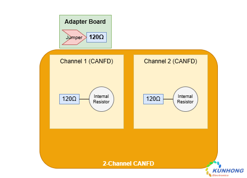
Although the resistance value still reads as 60 ohm, the effective termination position is not actually at the physical ends of the bus. This leads to a mismatch at the bus termination point and significantly degrades signal quality.
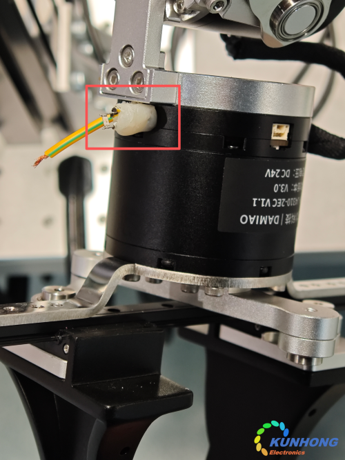
3. Grounding Issue: an Overlooked CAN Stability Factor
When checking OpenArm's CAN communication link, we also found another easy-to-overlook problem: the CAN cable harness does not provide a dedicated signal ground (GND).
In many "works-as-is" systems, it works because the negative terminal of the motor supply is indirectly connected through the power adapter and the CAN adapter's USB GND. While this may work in some cases, from an engineering standpoint it carries risk.
CAN receivers decide logic state based on the voltage difference between CANH and CANL, not on the voltage of a single line to ground.
Yet an easily missed issue remains: each node's transceiver still uses its local ground (GND) as the voltage reference.
If the ground potential difference between nodes exceeds the allowed range, you may see:
- Receivers unable to correctly interpret signals
- Signal edge distortion
- Increased communication errors
4. Why the System Still Communicates
Since OpenArm is open source, there have been many user reports about difficulty debugging and poor communication stability.
In our tests, we also found that different CAN adapters behave very differently. For example, when using classic CAN devices (PEAK CAN), the system cannot communicate at all. But with some modern adapters, such as KH-UCANFD or Pibiger, communication can work normally.
The reason is simple: many modern CAN adapters include additional optimizations, such as:
- Stronger signal tolerance
- Better analog filtering
- Smarter error recovery
This explains why OpenArm teams tested many USB-CANFD adapters, but only a subset worked. Even with higher-tolerance CAN adapters, OpenArm's underlying physical-layer deficiencies can still cause dropped frames or error frames.
"Can communicate" does not mean "reliable and stable". In this case, communication relies on consuming available CAN bus reliability margins. The consequence is that the system cannot stably run in industrial scenarios or complex operating conditions, or it may occasionally exhibit inexplicable issues, such as the common arm abnormal jerking and action inconsistency reported by many users.
5. Actual Remediation Process
Based on the issues above, we performed a simple CAN bus physical-layer remediation. The process mainly includes three steps.
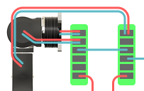
1. Optimize wiring
- Remove the original 60 cm dangling CAN stub directly
- Avoid long-distance parallel routing between CAN lines and the power lines
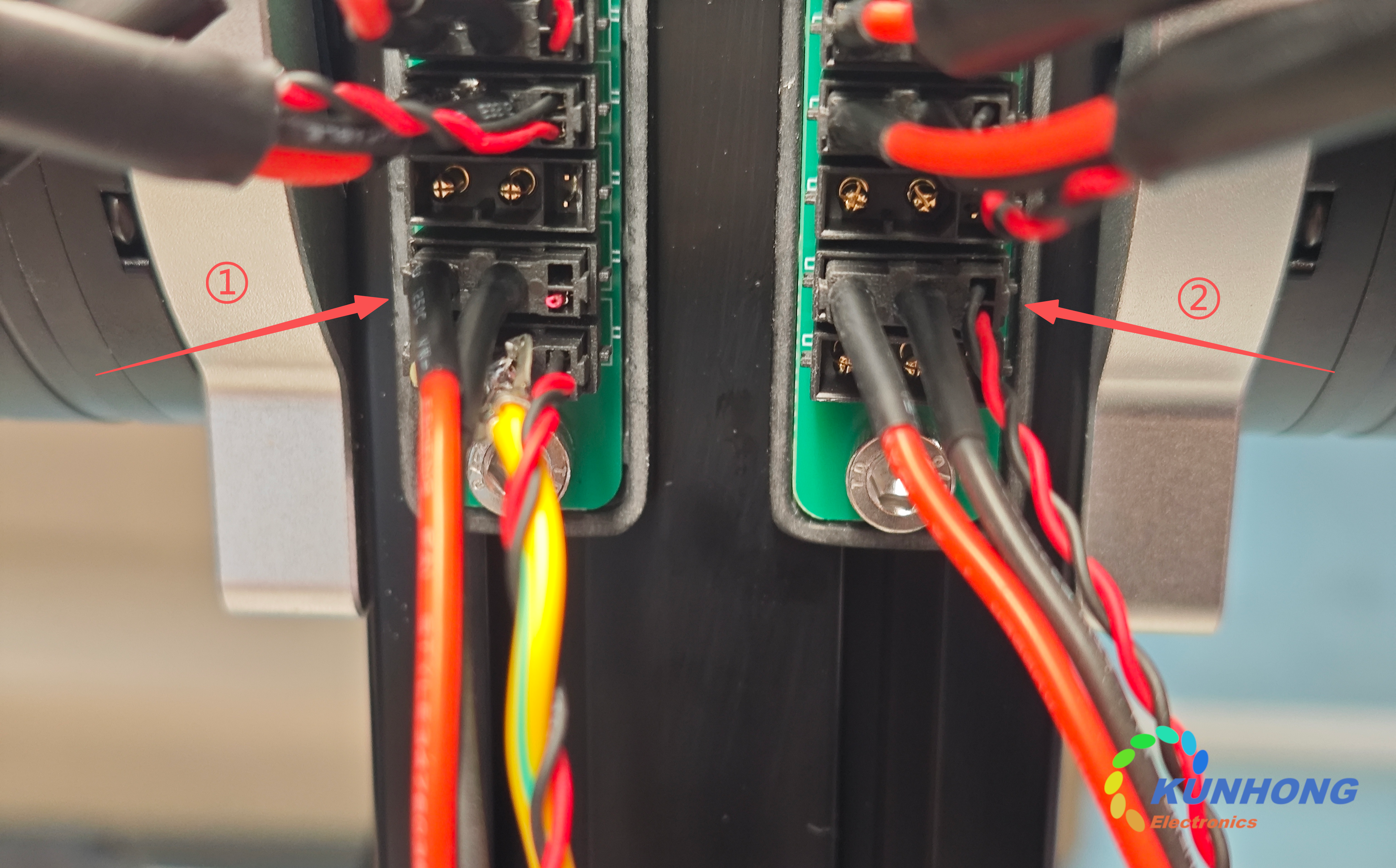
Part (2) is the original routing; part (1) is the optimized layout (removing the dangling branch and adding a ground connection).
2. Standardize termination resistors
Reconfirm the CAN bus termination resistor configuration:
- One 120 ohm termination resistor at each end of the bus
- No additional resistors in the middle nodes
- Remove the redundant termination resistor on the CAN adapter side (disable the adapter's internal software-controllable termination resistor, or remove the jumper cap on the DB9 adapter board)
- Add a 120 ohm termination resistor on the end motor (the J8 spare XT30 interface on the gripper/terminal motor)
3. Add a common ground connection
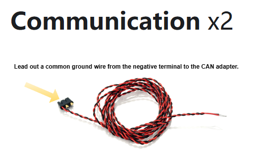
As a reference, connect a ground wire from the power negative terminal of the CAN wiring terminal to the CAN_GND of the CAN adapter.
- Since the DM motor does not provide a dedicated CAN_GND design, such motors can only use the power ground as the CAN_GND
6. Test Results After Remediation
We remediated one of OpenArm's arms and performed a comparative test with the other arm.
The results are very clear. After remediation, the arm:
- Works properly even with classic CAN equipment, and no longer shows communication anomalies (improves overall system compatibility)
- Shows significant improvement in oscilloscope observations:
- Signal reflections are reduced significantly
- Ringing basically disappears
- Edges become cleaner and more stable
- Bus errors disappear
Waveform before remediation:
Waveform after remediation(with KUNHONG KH-UCANFDX4):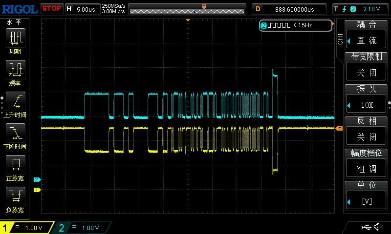
7. Conclusion
OpenArm, as an open-source project, is already very excellent by itself. Issues in communication-link engineering are also very common across many open-source hardware projects. Through a few simple engineering remediation steps, you can significantly improve system stability.
As practitioners, we should continuously contribute improvements and optimization efforts to open-source projects. We should not treat open-source materials as unchangeable originals or official artifacts; instead, we should help improve and iterate them so they become more complete and more valuable from an engineering perspective.
In a sense, the real value of open source is not only providing a system that can "run", but also improving it continuously through community iteration, making it more complete and more engineering-oriented.