
CAN Error Detection and Fault Confinement
CAN controllers check bit values, frame format and checksums while transmitting and receiving. When a controller detects an error, its state determines the error flag it sends. The transmitter normally retries the frame. As error counters rise, fault confinement reduces the effect a faulty node can have on other nodes.
Cable faults, interference, misplaced termination and node faults can all surface as protocol errors. The controller reports which rule was violated. Use the affected direction, node state and timing to narrow down the cause.
Five protocol error types
| Type | Detection condition |
|---|---|
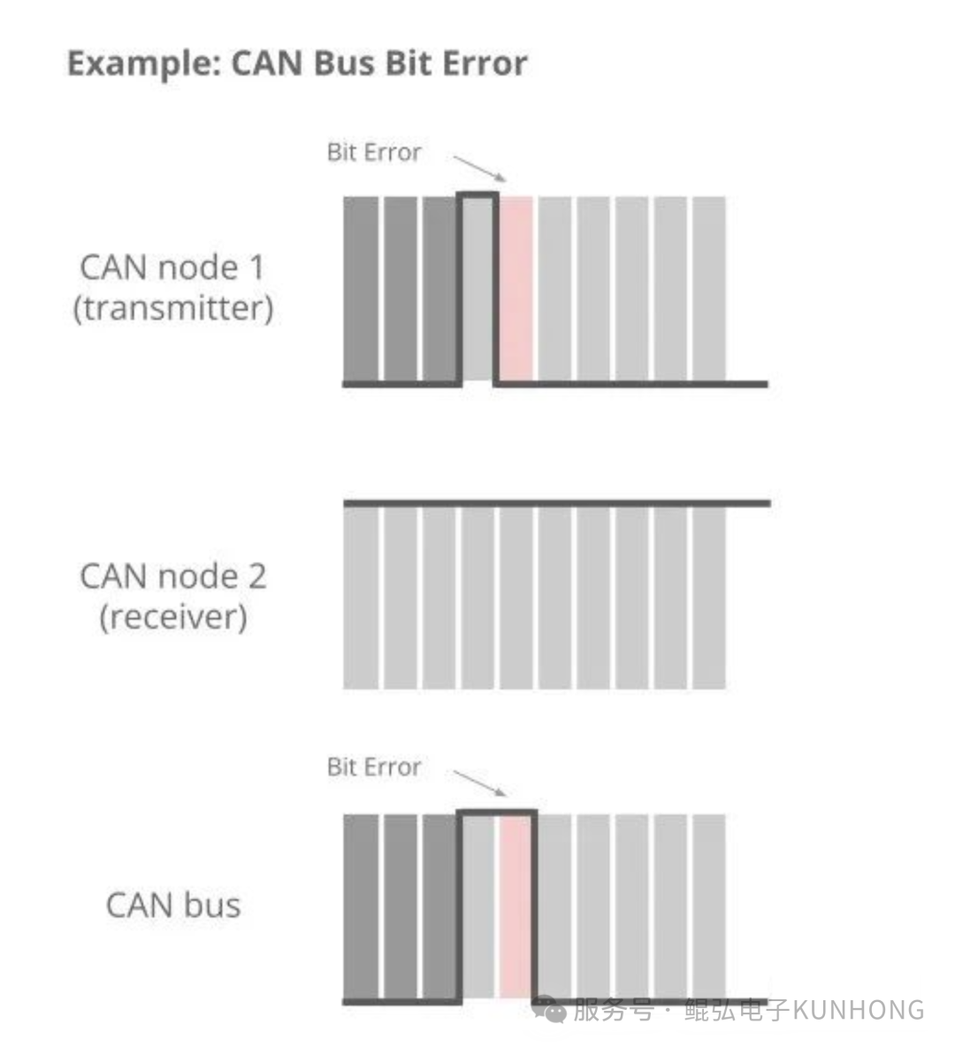
| Bit error | A transmitter reads a different bus value from the bit it sent. Reading dominant after sending recessive during arbitration can be a normal arbitration loss. The ACK slot also has its own rules. |
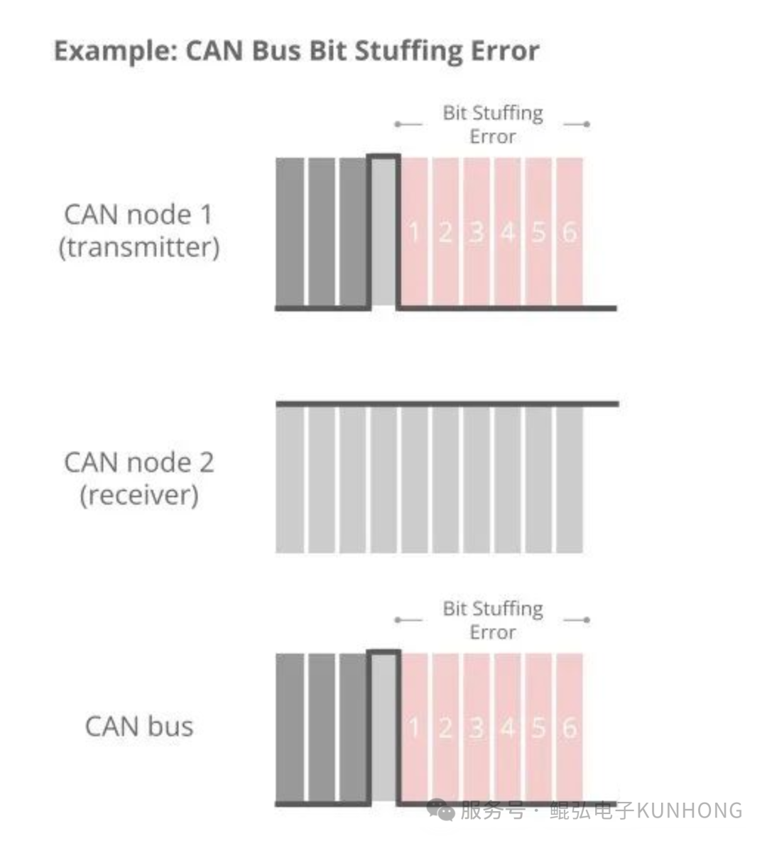
| Stuff error | A field violates its bit-stuffing rule. In a dynamically stuffed region, a complementary bit follows five consecutive bits of the same value. ISO CAN FD also uses fixed stuffing in its CRC region. |
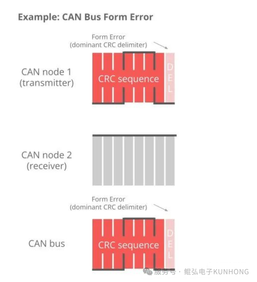
| Form error | A fixed-format field contains an illegal bit value, such as a dominant bit in a fixed recessive field at the end of a frame. |
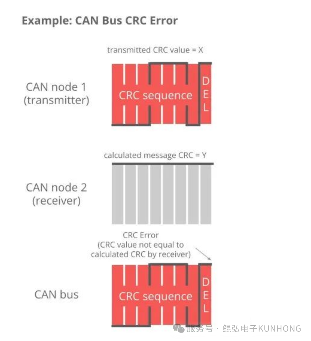
| CRC error | The receiver calculates a different CRC from the value carried in the frame. |
| ACK error | The transmitter sees no dominant bit in the ACK slot. Check that another enabled node can receive the frame correctly and acknowledge it outside listen-only mode. |
One physical problem can produce different error types at different nodes. Identify the affected interface and traffic direction, then check bit timing and wiring. Use the waveform simulator to locate stuff bits, CRC and the ACK slot in a normal frame.
What each error looks like
Bit error. The transmitter compares its output with the bus value in monitored fields. The marked bit differs in the illustration.
Stuff error. A sixth consecutive equal bit in a dynamically stuffed region lets the receiver detect a stuffing violation.
CRC error. The receiver calculates a CRC for the frame format and checks it against the received sequence.
Form error. Fixed fields such as the CRC delimiter have specified values. The example shows a dominant bit in the delimiter.
ACK error. The transmitter sends a recessive bit in the ACK slot. Other nodes that receive the frame correctly can drive it dominant. In the example, the slot stays recessive.
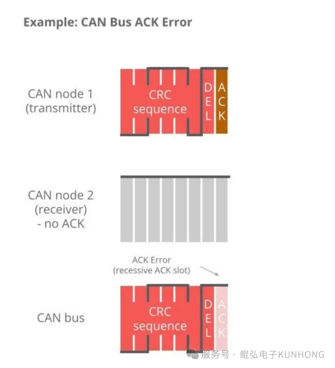
Error illustrations from CSS Electronics' CAN bus error tutorial.
Error states and counters
- REC (Receive Error Counter) tracks receive-side error handling. TEC (Transmit Error Counter) tracks transmit-side error handling. Changes depend on the node's role and error type. Successful transfers can bring the counters back down.
- Error Active applies when both counters are below 128. A node can signal a detected error with an active error flag of six dominant bits.
- Error Passive applies when TEC or REC reaches 128. The node can still transmit and receive. Its passive error flag consists of six recessive bits.
- Bus-Off occurs when TEC reaches 256. The node stops communicating on the bus. Find the cause of the transmit errors before recovering the node through the controller or driver.
These thresholds describe protocol state. Some controllers expose limited-width counters together with status bits. For intermittent faults, use cumulative statistics and captures alongside counter readings, which may already have fallen. See the Bosch CAN controller manual.
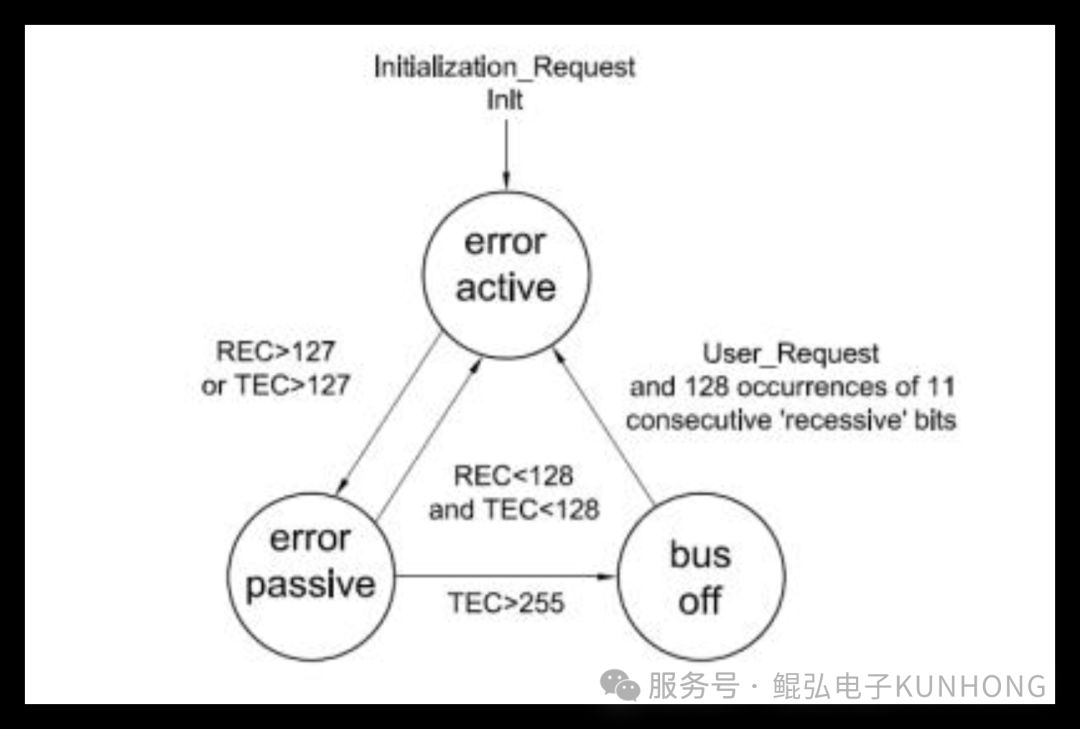
Interpret changes in the counters
For example, sending an error flag as a transmitter generally increases TEC by eight. A successful transmit can lower TEC by one. A receiver that detects an error generally increments REC by one. The protocol defines exceptions for particular errors and node roles.
- Intermittent interference. One error can raise a counter sharply. Successful transfers can then bring it down over time. Compare readings from nearby points in time with a record of error events.
- Persistent faults. If errors keep increasing the counts, the node can become Error Passive and repeated transmit errors can lead to Bus-Off. Counter changes depend on the error type, node role and protocol exceptions. Check the controller state and error records together.
Inspect errors reported by the device
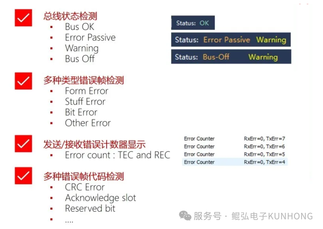
Check the reported bus state, REC/TEC and error categories available for your device, firmware and driver. On Linux, kcan_monitor from the Kunhong SDK can monitor supported channels continuously. Its rec/tec columns show the receive and transmit error counters, and err shows the cumulative error count.

Continue troubleshooting
Originally published by Kunhong R&D on 2025-12-17 as CAN Bus Error Detection Explained.