
Improve the CAN Physical Link on an OpenArm
The CAN nodes on one OpenArm arm follow a trunk, with short branches to J1 and J2. If you see frame errors, intermittent communication or Bus-Off, check the harness from the hub to the power connector, termination at the adapter and breakout board, and the adapter's CAN-side ground reference.
Remove the open stub in the power harness
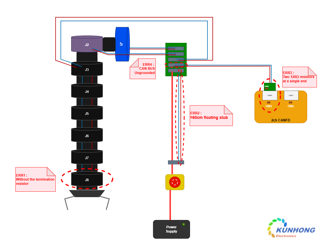
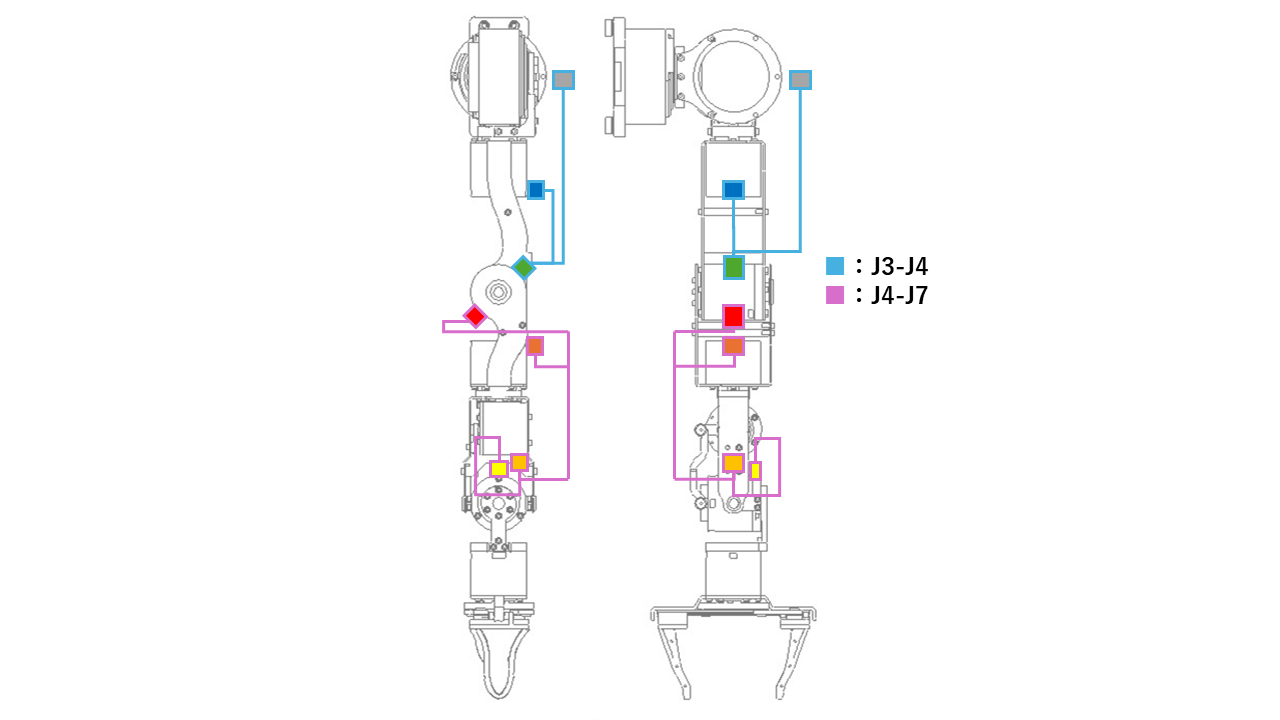
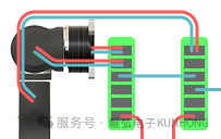
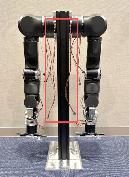
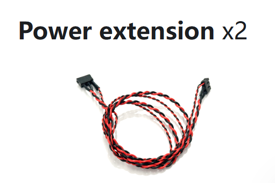
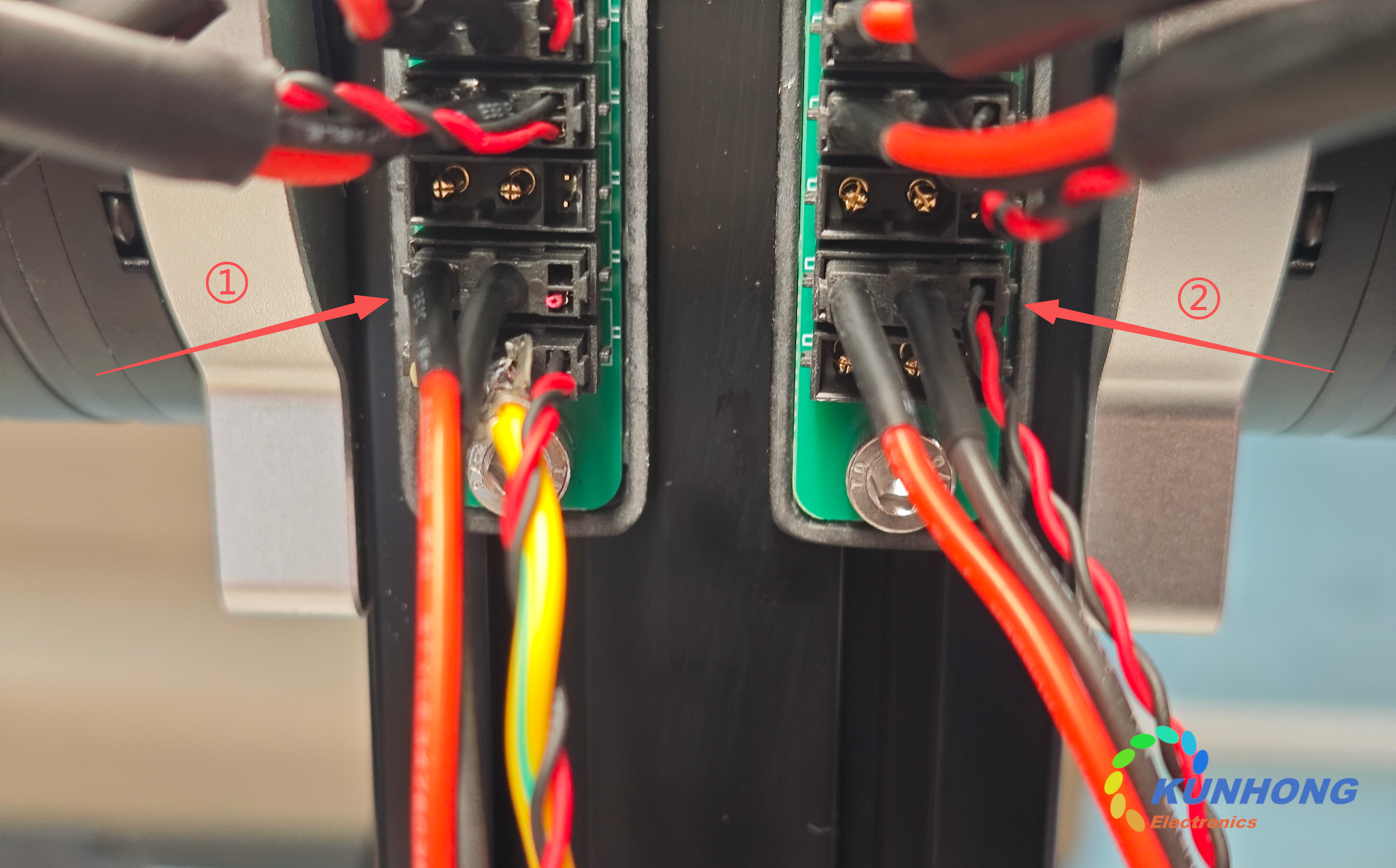
In this case the power extension also carried CAN_H and CAN_L from the hub, creating an open stub about 60 cm long. With no node at the end, the stub can reflect signal edges back onto the trunk and cause ringing. Power down and check the harness pinout and continuity. Keep only the necessary power wires on the run from the hub to the power connector. Route the trunk's CAN_H and CAN_L together, keep stubs short and avoid long parallel runs beside motor power wiring.
Put one terminator at each end
The adapter's internal 120 Ω resistor and the DB9 breakout's 120 Ω resistor were both at the same end. They could still read about 60 Ω in parallel while leaving the far end of the arm unterminated.
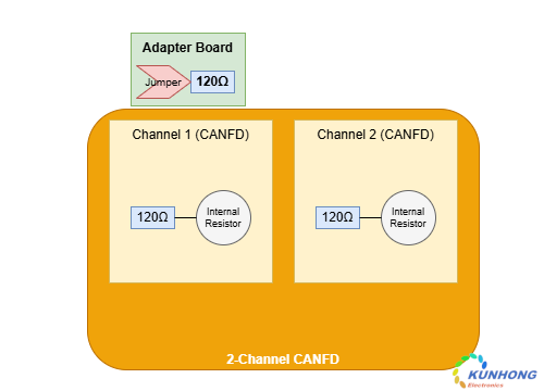
- Disable the adapter's internal terminator or remove the breakout jumper so only one 120 Ω terminator remains at the adapter end.
- Add 120 Ω at the far end. In the illustrated layout, use the spare XT30 connector at the J8 gripper. Check the pinout and place the terminator across CAN_H and CAN_L.
- With power off, measure resistance between CAN_H and CAN_L and confirm the physical location of both terminators. CAN wiring troubleshooting
Check the CAN ground reference
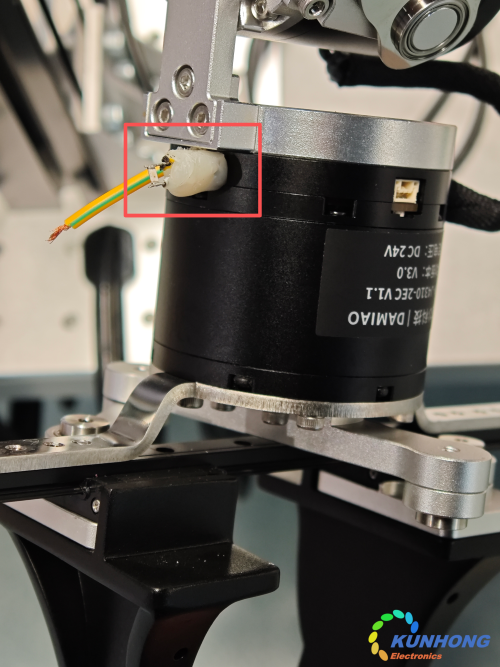
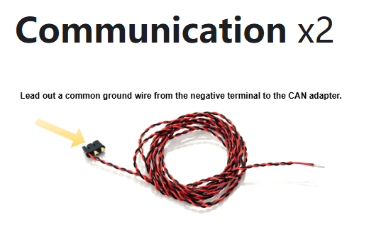
Differential reception still depends on the transceiver's common-mode range. Confirm the CAN_GND reference path and isolation boundaries against the motor and adapter pinouts. In this case the motor uses its power return as its CAN-side reference. A reference wire can run from that point in the harness to the adapter's CAN_GND. Confirm the pinout before connecting and maintain any isolation required by the equipment.
With only CAN_H and CAN_L in the harness, the reference path may run indirectly through the supply or USB ground. Check reference continuity and the transceiver's common-mode range when changing the wiring. This helps preserve the ground reference when swapping adapters or power supplies. Joint motor CAN connectors and harnesses
Recheck each change
Keep frame type, bit rate and transmission period the same while checking interface state and error statistics after each change. If you use an oscilloscope, compare reflections and ringing at the same measurement point. Follow the OpenArm debugging workflow to check a single motor before bringing the full arm back into operation. If errors persist, record traffic using the SocketCAN troubleshooting guide.
Inspect edges and ringing
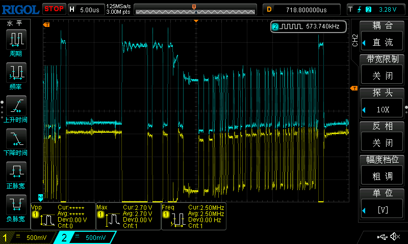
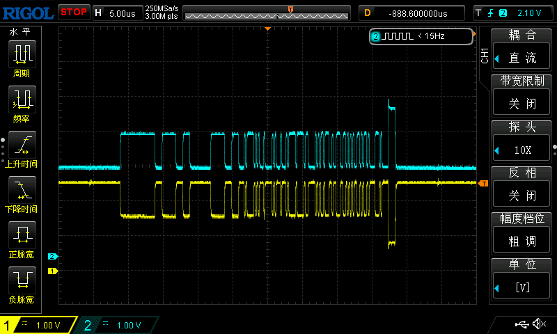
The original wiring example shows more overshoot and ringing. The rewired example has cleaner edges. Read both images with their voltage and time scales. On your own bus, compare waveforms and error statistics under matching conditions to see which wiring change affects the link.
Receiver circuitry and error reporting can vary between adapters. When traffic is flowing, still check termination placement, ground reference and error rates, especially with several joints active.
Originally published by Kunhong R&D on 2026-03-20 as the OpenArm CAN Communication Link Optimization Guide.