
Troubleshoot CAN Bus Wiring
When a high-speed CAN or CAN FD link shows errors, dropped frames or Bus-Off, check termination, topology, cabling and signal ground in that order. Record interface state and traffic during the fault, then power down to inspect the wiring.
Once the wiring meets the equipment requirements, check frame format, bit rates, sample points and CAN FD data-phase settings. SocketCAN troubleshooting · CAN/FD bit timing
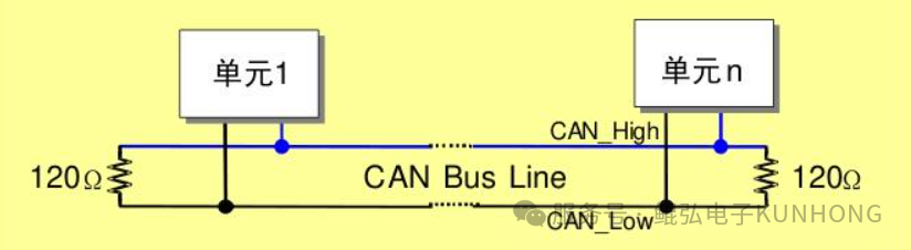
Check termination resistance and location
- Find both physical ends of the trunk and confirm one 120 Ω terminator at each end. Check whether the adapter and breakout board each have their own terminator.
- Switch off power to the bus nodes and confirm there is no voltage before measuring between CAN_H and CAN_L at an accessible point. If an electronic terminator opens when power is removed, follow the device manual to check its switch state and resistance independently.
- Use the reading to narrow down the fault and check where the terminators are connected. Two 120 Ω resistors at the same end can also read approximately 60 Ω.
| Reading | What to check |
|---|---|
| About 60 Ω | Usually two 120 Ω resistors in parallel. Confirm one at each end of the trunk. |
| About 120 Ω | Look for a missing, disabled or disconnected second terminator. |
| Well below 60 Ω | Look for extra termination, the wrong resistance or a short. |
| High or open | Check for missing termination, disconnected wiring or a measurement point off the trunk. |
See Kvaser's CAN termination check and Fluke's resistance measurement steps.
Check topology, cabling and signal ground
- Trunk and stubs. Prefer a linear trunk. Keep stubs short and remove lines that end without a node. Star and multilevel branches add impedance discontinuities that can cause reflections and ringing.
- Cable. Route CAN_H and CAN_L together as a twisted pair suitable for the bus. Avoid long parallel runs next to motor power cables or switching nodes. Trunk and stub limits depend on bit rate, transceivers and topology. For CAN FD, check the data-phase rate as well.

Keep both terminators at the ends of the trunk when using stubs. Longer stubs and more branches call for closer attention to drive capability and reflection margin. Check permissible lengths against the transceivers, cable and bit rates.
| Bit rate | Classical CAN wiring reference |
|---|---|
| 1 Mbit/s | CiA gives 25 m for CANopen CC and 40 m as a theoretical example for CAN HS. |
| 500 kbit/s | 100 m |
| 250 kbit/s | 250 m |
| 125 kbit/s | 500 m |
| 50 kbit/s | 1,000 m |
Use these lengths for planning under the relevant Classical CAN conditions. For CAN FD, check both bit rates, propagation delay and stub layout. CiA CANopen CC timing table · CiA high-speed CAN overview
Check the signal ground reference
The differential receiver reads the difference between CAN_H and CAN_L, and each node still has a local reference potential. A ground potential difference close to or beyond the transceiver's common-mode range can cause errors, loss of communication or damage.
- Check CAN_GND, supply return and isolation boundaries against the interface pinout. With power off, use a continuity test at reference points the design connects.
- If you suspect a ground potential difference during operation, follow the equipment instructions for voltage measurements between the relevant reference points. Compare against the transceiver's common-mode range. Use differential or isolated measurement equipment appropriate to the point when checking transients during motor operation.
Change one connection at a time and recheck interface state and error statistics. See the OpenArm link case study for a duplicate terminator and dangling stub, and the SocketCAN troubleshooting guide for software-side checks.
Originally published by hoyo on 2026-01-09 as CAN Communication Troubleshooting: Wiring Faults.