
DB9 Adapter V2.4
The PCIE_DB9_GH1.25_V2.4 routes one GH1.25 CAN / CAN FD channel from a KH-UCANFD-M2 or KH-UCANFD-MP card to a male DB9 connector. Each adapter serves one CAN channel.
Appearance and 3D Model
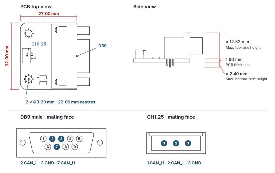
Mounting Dimensions
| Item | Dimension |
|---|---|
| PCB outline | 27.00 × 32.00 mm |
| PCB thickness | 1.60 mm |
| PCB mounting holes | 2 × Ø3.20 mm, 22.00 mm centre to centre |
| Maximum top-side component height | Approx. 12.52 mm |
| Maximum bottom-side protrusion | Approx. 2.40 mm |
Heights are measured from the corresponding PCB face. The DB9 connector projects approximately 6.11 mm past the PCB edge, giving an assembled dimension of approximately 33.11 mm along the 27 mm side. Allow clearance for the mating plug and cable.
Connector Pinout
The GH1.25 header is a Bossie BX-GH1.25-3PWT with three pins on a 1.25 mm pitch. The drawing shows both connectors viewed from their mating faces.
| Signal | GH1.25 pin | DB9 pin |
|---|---|---|
| CAN_H | 1 | 7 |
| CAN_L | 2 | 2 |
| CAN GND | 3 | 3 |
| Unconnected | — | 1, 4, 5, 6, 8, 9 |
Use a three-wire cable to connect the adapter to the required CAN channel, matching CAN_H, CAN_L, and GND. Check the pinout of the mating DB9 device before connecting it. Use the DIP switch for the corresponding channel on the M2 or MP card to configure bus termination.