In-Depth Analysis: Automotive Ethernet (100/1000BASE-T1) Technical Principles and Application Guide
With the rapid development of new energy vehicles toward intelligence and connectivity, bandwidth and transmission rates have become core bottlenecks. Traditional CAN bus struggles to meet massive data transmission requirements, leading to the emergence of Automotive Ethernet protocols such as 100BASE-T1 and 1000BASE-T1. This article systematically analyzes the fundamental concepts of Automotive Ethernet protocols and outlines technical points and debugging strategies for practical engineering applications.
I. Basic Concepts and Definitions
Automotive Ethernet is a physical layer standard optimized for harsh vehicle environments, including strong electromagnetic interference and temperature fluctuations.
Protocol Standards
| Protocol | Release Date | Bit Rate | Description |
|---|---|---|---|
| 100BASE-T1 | 2015 | 100 Mbit/s | IEEE 802.3bw |
| 1000BASE-T1 | 2016 | 1 Gbit/s | IEEE 802.3bp |
Core Features
| Feature | Description | Advantages |
|---|---|---|
| Transmission Medium | Single-pair Unshielded Twisted Pair (UTP) | Reduces cable usage by 75% compared to standard Ethernet, lowering weight and cost |
| Transmission Distance | Supports 15 meters in-vehicle wiring | Perfectly covers distances between domain controllers and nodes throughout the vehicle body |
| Interference Resistance Design | Echo cancellation, common mode suppression technology | Meets stringent automotive EMC standards (ISO 11452-2) |
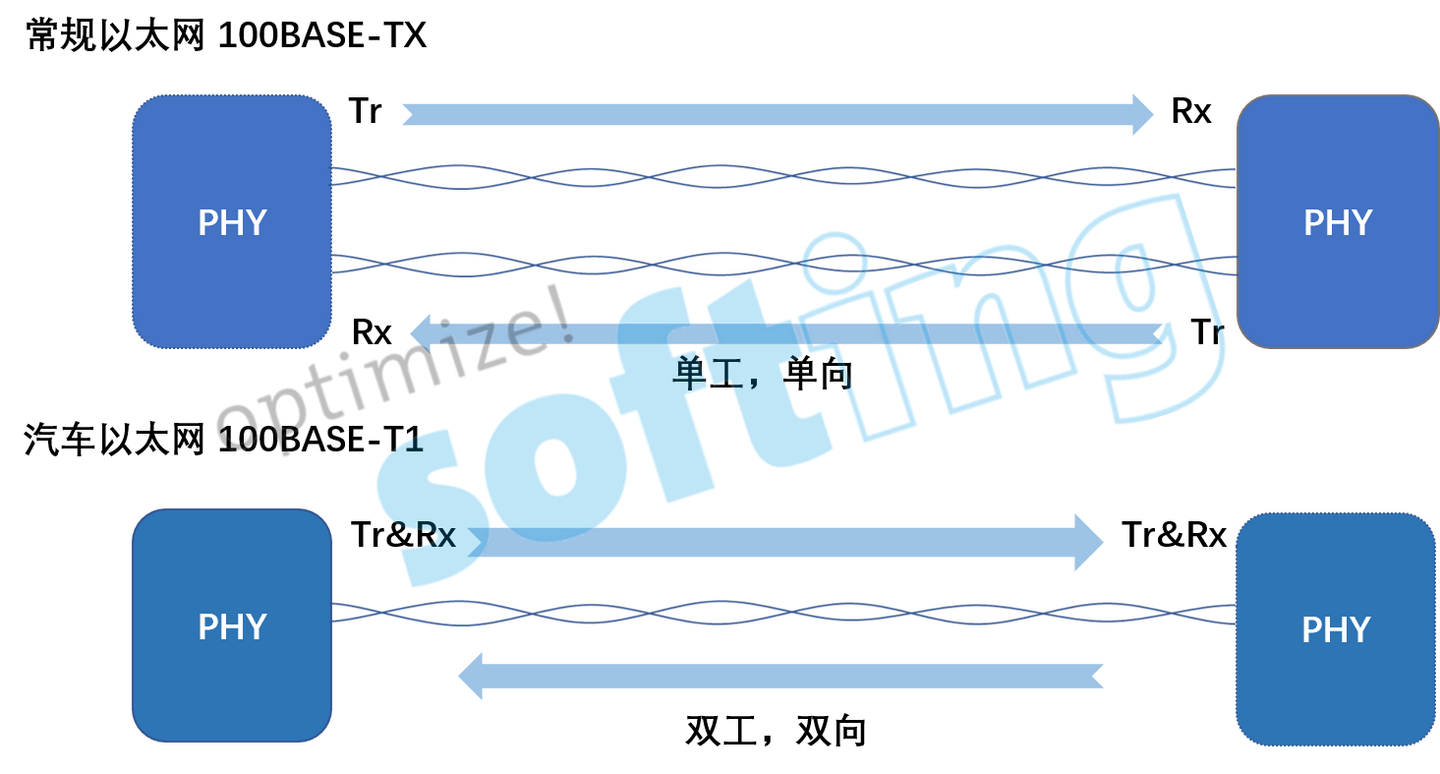
| Duplex Mode | Full-duplex communication | Supports simultaneous send and receive of data, avoiding the collision detection mechanism of traditional Ethernet |
II. Technical Comparison: Why Choose Automotive Ethernet?
1. Comparison with Traditional CAN Bus
Topology Differences: CAN adopts bus topology, where all nodes are connected to the same bus; Automotive Ethernet adopts star topology.
Performance Improvement: Point-to-point communication significantly enhances communication reliability and substantially accelerates response time for urgent events.
2. Comparison with Standard Ethernet (RJ45)
Physical Layer Differences:
- Standard Ethernet typically requires 4 pairs of twisted pair
- Automotive Ethernet requires only 1 pair
Advantages: In the space-constrained vehicle interior, this has decisive significance for simplifying harness design and reducing overall vehicle weight.
III. Key Prerequisites for Establishing Connection (Link Up)
When building and debugging Automotive Ethernet, physical layer connection (Link Up) is the foundation for communication. The following points must be noted:
1. Speed Matching
Communication parties must be configured to the same speed (both 100 M or both 1000 M) to establish connection.

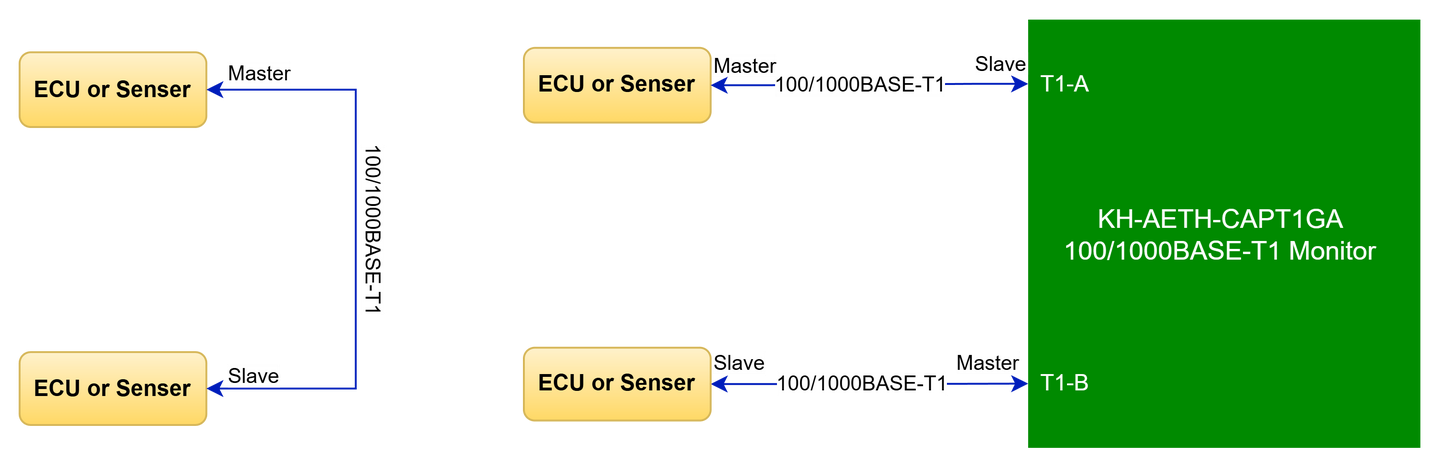
2. Master/Slave Mode
Unlike standard Ethernet's auto-negotiation, 100/1000BASE-T1 requires pre-configuration of the PHY layer roles.
Rule: Must follow the "one Master, one Slave" correspondence relationship.
Note: The Master/Slave here refers only to the clock synchronization role during physical layer training, not the Master/Slave relationship of upper-layer data communication. Once Link Up is successful, both parties can actively send and receive data.
3. Interface System
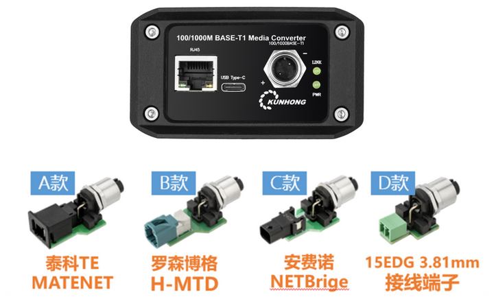
In the evolution of Automotive Ethernet, to meet the stringent special requirements of the vehicle interior—such as extreme space limitations, higher transmission rates, and high-standard interference resistance (EMC)—physical interface designs have gradually departed from the traditional RJ45 form, forming a diversified automotive-specific interface system (such as TE MATEnet, Rosenberger H-MTD, etc.).
The diversity of these interfaces brings challenges to development and testing. To adapt to different vehicle models and controller interfaces, supporting test equipment typically faces two choices:
Customized Interfaces: Integrate specific automotive interfaces directly on the device. However, this leads to significant increases in device cost and poor universality.
Flexible Adapter Solution (Recommended): As shown in the figure below, adapt by providing high-quality adapter boards or adapter cables. This approach can ensure signal quality while accommodating different interface standard switches at lower cost, greatly enhancing testing convenience.
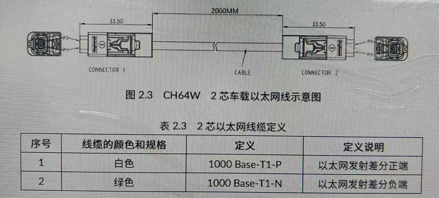
4. MDI Polarity and Auto-Swapping
Polarity refers to the positive/negative connection of differential signals (P ↔ P; M ↔ M).
| Protocol | Auto-Correction Function | Recommendation |
|---|---|---|
| 1000BASE-T1 | Most PHY chips have auto-correction capability | Can establish connection even if reversed by detecting signal phase automatically |
| 100BASE-T1 | Some devices in Slave mode support auto-correction | Strongly recommend strictly checking polarity during wiring to ensure connection stability |
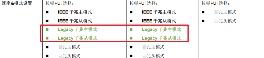
5. Legacy Mode (Special Case)
Background: Before IEEE standards matured, Marvell introduced early Gigabit T1 PHY chips (Legacy mode).
Current Status: Currently mainly exists in some early Tesla vehicle models. Since this mode is incompatible with standard IEEE mode, it's necessary to confirm whether the device supports it during debugging (Note: There is no Legacy distinction for 100 Mbit/s mode).
IV. Communication Quality Diagnostics
After connection is established, link quality directly determines the stability of data transmission.
1. SQI (Signal Quality Index)
PHY chips can monitor SQI values in real-time. This is an important basis for judging the degree of link impedance matching and the impact of environmental interference.

2. Cable Health Detection
Harness material, length, twist pitch, and connector characteristics can all lead to impedance changes. Professional detection tools (such as RAD.NEPTUNE) can assist in diagnostics:

Detection Items:
- Insertion Loss (IL)
- Return Loss (RL)
Principle: Use Time Domain Reflectometry (TDR) to locate fault points such as short circuits, open circuits, and impedance mismatches.
Note: Parameters provided by the device are primarily for rapid on-site troubleshooting and comparison. For high-precision cable certification, it is recommended to use professional laboratory instruments.
V. Debugging Solution: How to Connect PC with Automotive Units?
Pain Points
Standard IT equipment (PC, switches) uses standard Ethernet interfaces (RJ45) and cannot communicate directly with Automotive Ethernet devices (ECU, LiDAR).
Solution: Physical Layer Converter
Use Ethernet physical layer converters (Media Converter) to perform lossless conversion of physical layer signals at both ends.
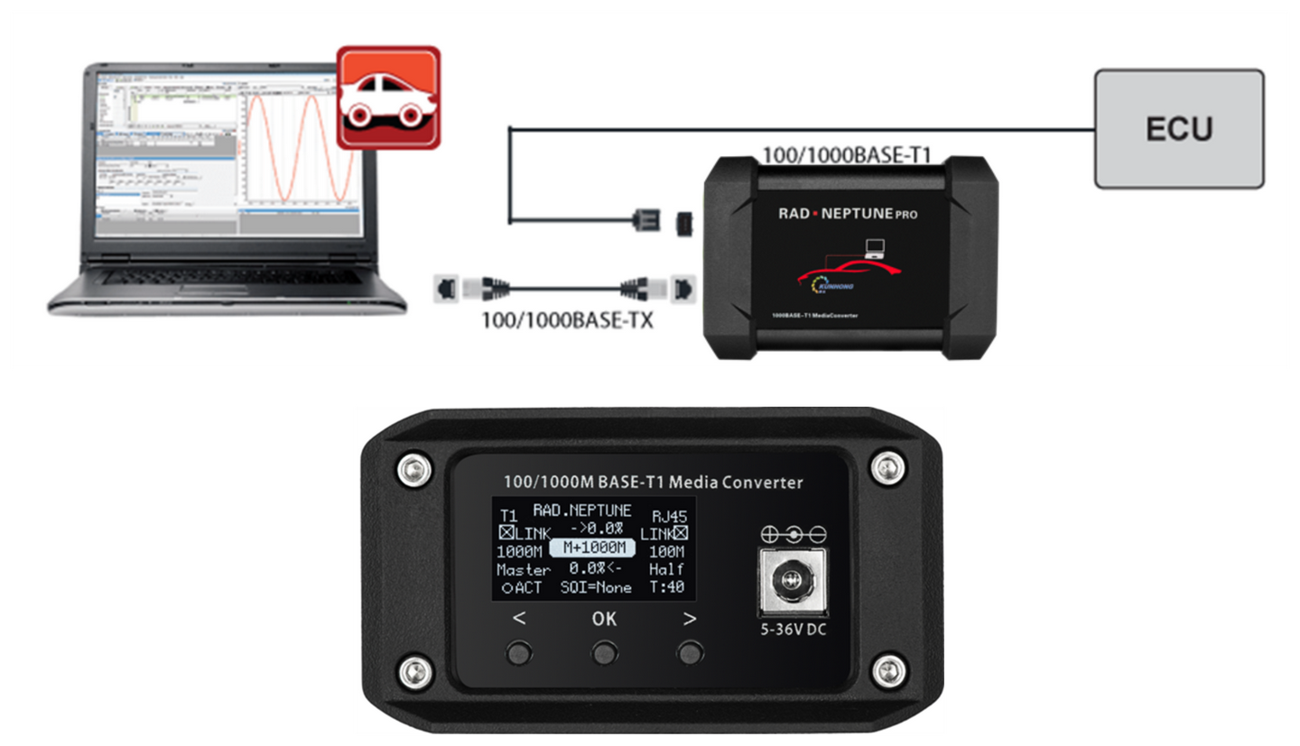
Principle: After Link Up on both ends of the converter, it's equivalent to a "transparent" network cable.
Effect: Data passing through the converter undergoes no protocol-level changes, and latency is extremely low.
Recommended Tool: RAD.NEPTUNE
RAD.NEPTUNE is a professional Automotive Ethernet physical layer conversion module, specifically designed for debugging scenarios:
| Feature | Description |
|---|---|
| Multi-Rate Support | Compatible with 100/1000BASE-T1 and standard Ethernet conversion |
| Smart Matching | Capable of automatically recognizing and matching automotive ECU's Master/Slave mode and speed |
| Visual Debugging | Equipped with OLED display, showing configuration mode, connection status (Link Status), and communication quality in real-time, significantly improving debugging efficiency |