Automotive Ethernet Converter - Practical Application Guide
This article will introduce how to use Automotive Ethernet converters to quickly get started with Automotive Ethernet physical layer.
I. Simplest Automotive Ethernet Environment
Environment Preparation
- Prepare one computer, connected to router via network cable for internet access

Setup Steps
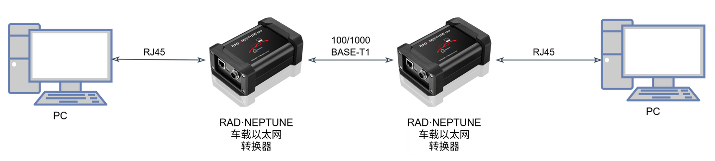
Connect two Automotive Ethernet converters in series between computer and router:
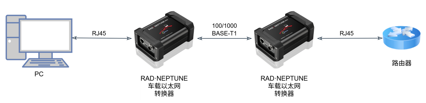
Function of Automotive Ethernet Converter: Converts between standard Ethernet and Automotive Ethernet.
Through two converters, the network path becomes:
- Standard Ethernet → Automotive Ethernet → Standard Ethernet
After the converter link is established, it functions like a special network cable, and the computer can still access the internet normally.

II. Automotive Ethernet 100/1000BASE-T1 Physical Layer Basic Concepts
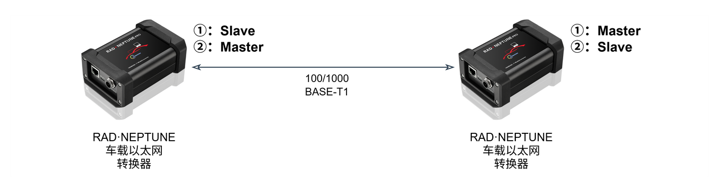
Master/Slave Mode
Automotive Ethernet devices must follow the "one Master, one Slave" correspondence relationship to establish Link connection.
Speed Matching
The converter supports 100/1000BASE-T1 specifications. Standard Ethernet devices and Automotive Ethernet devices must have matching speeds to communicate normally.
- Both at 100 Mbit/s
- Both at 1000 Mbit/s
III. Testing Impact of Different Cables on Physical Links
SQI (Signal Quality Index)
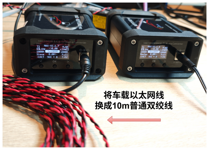
SQI value is an important basis for judging Automotive Ethernet communication link quality. The converter can directly view SQI changes through the screen.
Example: Replace the Automotive Ethernet cable with 10-meter long standard twisted pair, and both converters display SQI value of 8.
Description: Higher values indicate better quality, with maximum of 15.
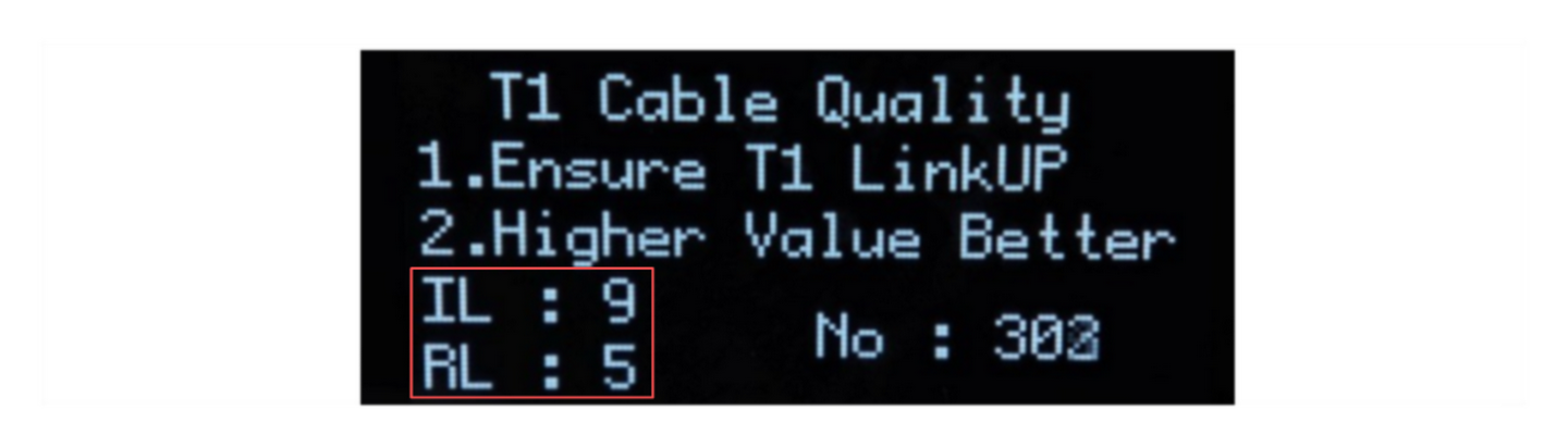
Cable Quality Detection
The converter supports detection of the following parameters:
- Insertion Loss (IL)
- Return Loss (RL)
Detection Principle: Use Time Domain Reflectometry (TDR) to determine communication cable quality, capable of diagnosing following issues:
- Short circuits
- Open circuits
- Communication cable impedance mismatch
- Faulty connectors
- Termination mismatch
Description: Higher values indicate better quality, with maximum of 15.
Note: Precise cable quality detection still requires professional equipment. Parameters provided by this device are for reference and comparative use only.
Impact of Distance and Cable Material on Communication
Combining SQI values as well as IL and RL data, qualitative analysis can be performed for:
- Cable quality (good or bad)
- Communication distance
- Impact on Automotive Ethernet communication quality
IV. Speed Testing Considerations
The iperf tool can be used to test maximum network bandwidth.
Test Method
Replace the router in the environment with a second PC:
Server (PC A) Execute:
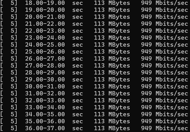
iperf3.exe -sClient (PC B) Execute:
iperf3.exe -c 192.168.xx.xx # Specify server IPTest Result: Taking 1000BASE-T1 as an example, after passing through Automotive Ethernet converters, test results show that it can maintain 949 Mbits per second, verifying that the converter does not affect communication rate.
Recommendations for Improving Test Accuracy
Test results may be affected by environmental factors, potentially causing rate instability. The following aspects can improve accuracy:
- Use high-performance CPU computer, and do not limit its performance
- Close other software applications
- Set test process to highest priority
V. Automotive Ethernet Troubleshooting
When building networks, communication anomalies are inevitable. Taking this setup environment as an example, troubleshooting can be performed through following points:
Link Status
The LINK status at both ends of the converter can be observed through the screen.
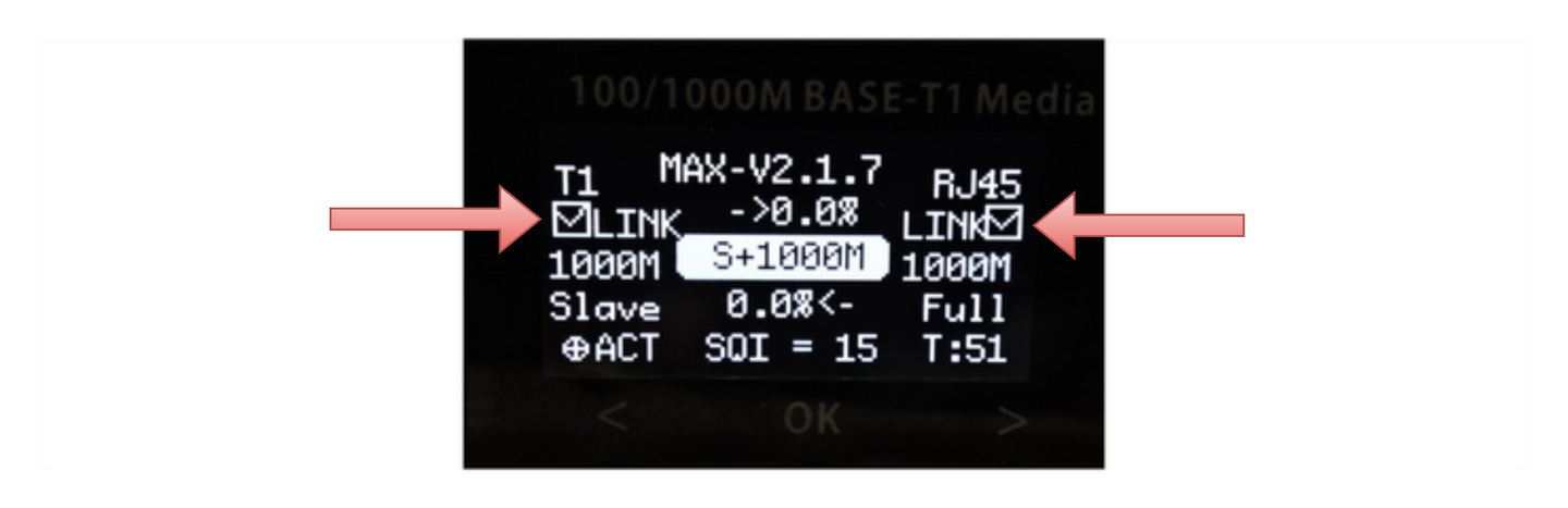
- If displayed as "×", it indicates abnormal connection between converter and adjacent device
Need to Confirm:
- Whether physical line connection is normal
- Whether the peer is in connection-waiting state
- Whether both ends have matching Master/Slave status and speed
Indicator Lights
Through indicator lights, it can be quickly determined whether data is passing through the converter.
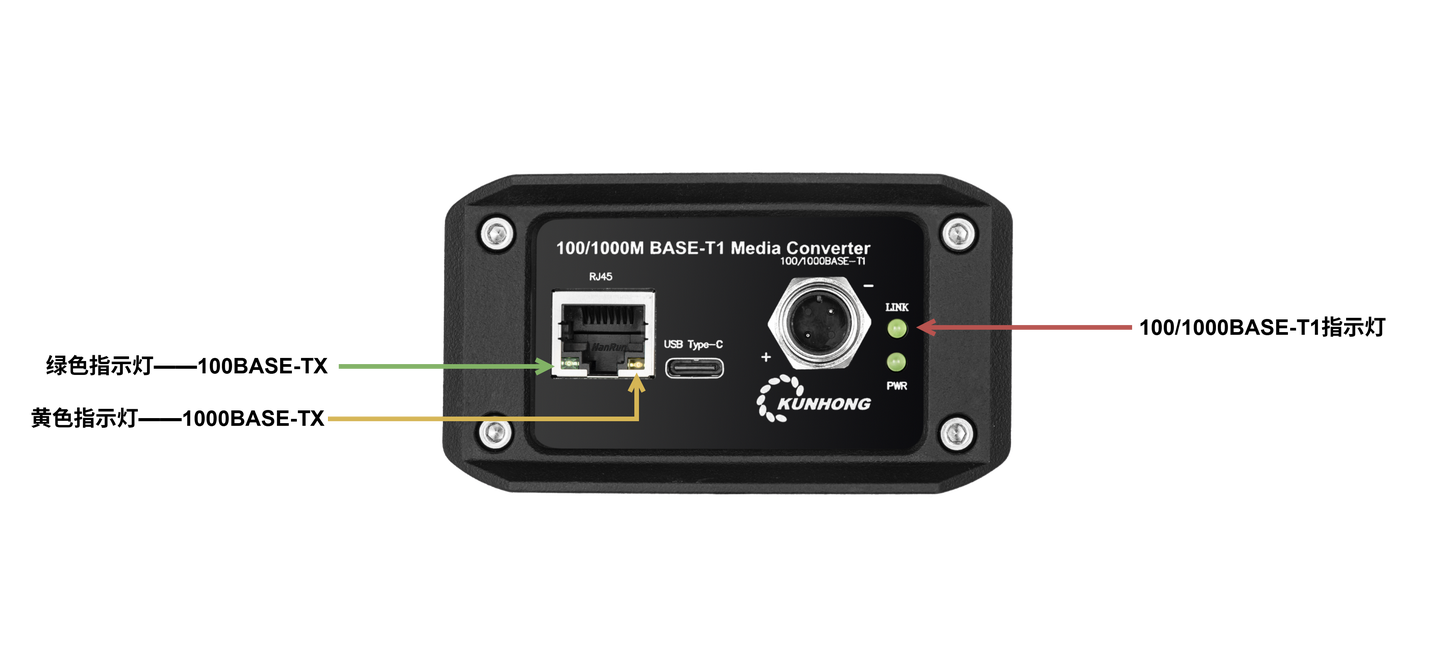
Normal Operating State:
- When data passes, T1 and TX indicator lights flash simultaneously (1-2s delay)
.gif)
Abnormal Situation:
- Troubleshoot issues on corresponding directional ports through abnormal indicator lights
Packet Counter
Confirm link status through the built-in receive packet counter of the converter device.
- If the receive packet counter increases, it indicates normal physical link with the peer device
- Conversely, need to troubleshoot physical link issues
VI. Standard Ethernet Troubleshooting
As mentioned previously, when the converter successfully converts the network, it's equivalent to a special network cable and does not affect MAC and above-layer protocols, meaning it does not affect frame transmission.
If the converter works normally but communication is abnormal, how should further troubleshooting be performed?
Test Environment Troubleshooting
For this article's test environment, you can remove the 2 converters and troubleshoot network configuration issues after direct cable connection.
Actual Automotive Environment Troubleshooting
If connecting to actual automotive equipment, troubleshooting can be performed from the following two aspects:
IP and Network Configuration
DHCP Automatic Acquisition
- Check whether DHCP related configuration is enabled
Static IP
- Ensure correctness of IP address, subnet mask, and other settings
Other Network Configuration
- Check firewall and other network configurations
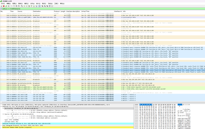
Using Wireshark for Packet Analysis
Wireshark can be used to exclude local network card MAC address to check whether frames from other devices are received, thereby confirming physical link status.
Operation Steps:
- Find Local Network Card MAC Address

Filter Out Self-Sent Frames in Wireshark
!(eth.src == 7c:4d:8f:a4:aa:3a) # Replace with actual MAC address
Judgment Criteria:
- If unable to receive frames, physical link problem may exist
- If frames can be received, further analysis can be performed based on frame content